Company Logo

Unpacking Traditional Datacenter Cooling Systems

From Chip to Atmosphere: The Heat's Journey

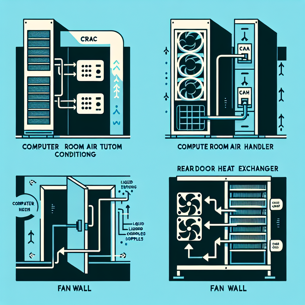
Having established the critical nature of datacenter cooling in the age of AI, this article delves into the mechanics of traditional cooling systems. These air and water-based technologies form the backbone of today's digital infrastructure, representing sophisticated engineering solutions developed over decades to manage ever-increasing thermal loads.

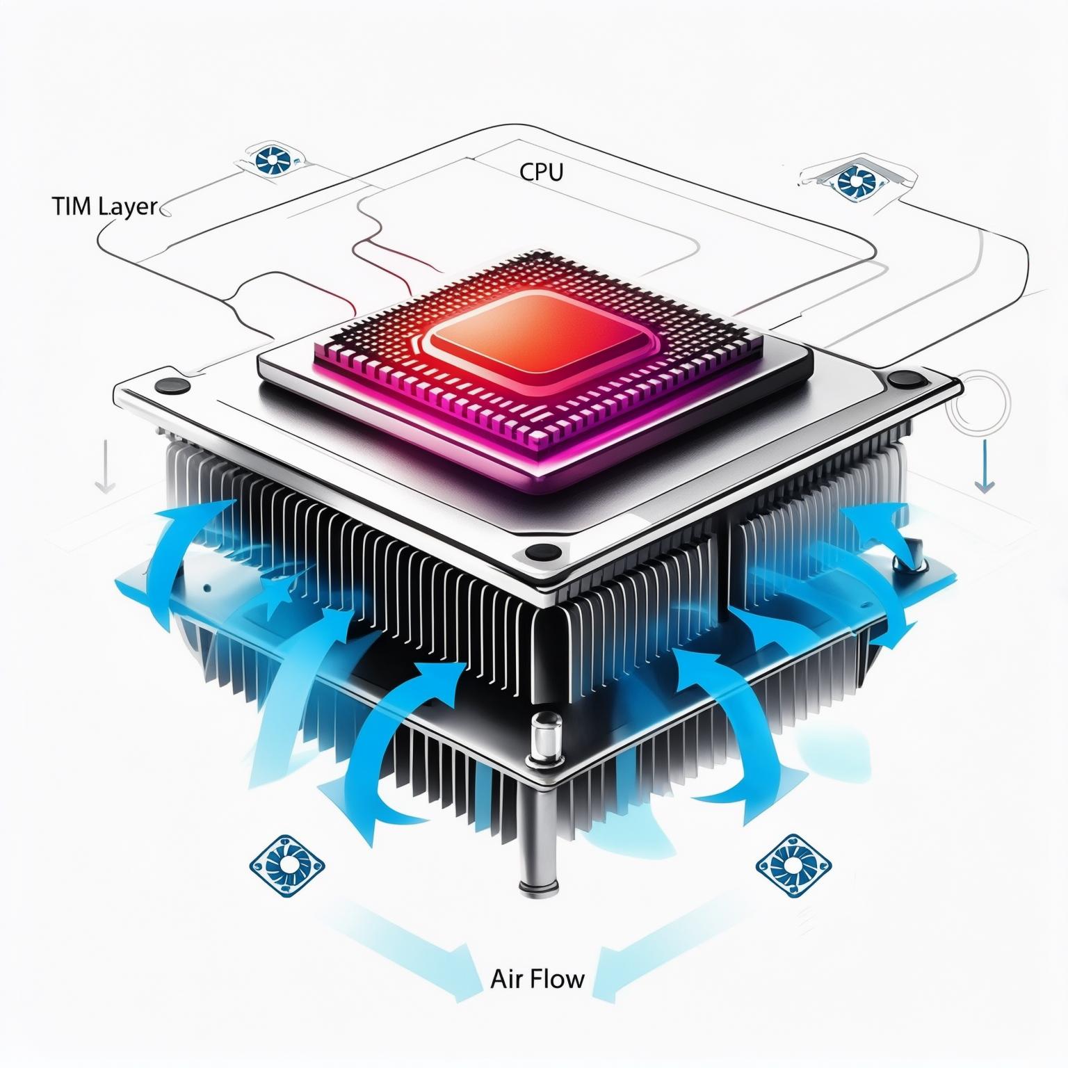
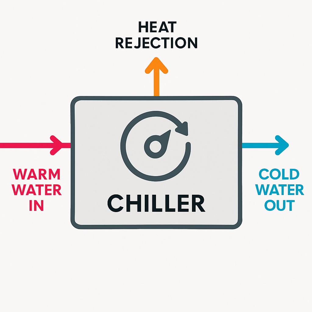
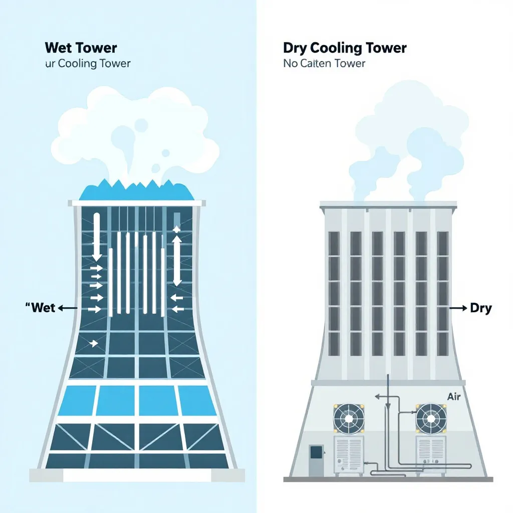
Understanding the components and the pathway heat takes from the server chip all the way to the outside environment is fundamental. We'll trace this journey through the core systems that maintain the operational temperature of hyperscale facilities.

Simplified schematic diagram illustrating the heat flow path in a datacenter: Server -> Indoor Unit -> Chiller/Tower -> Outside. Use clear icons, arrows, and color changes (blue=cool, red/magenta=hot) to show the flow.

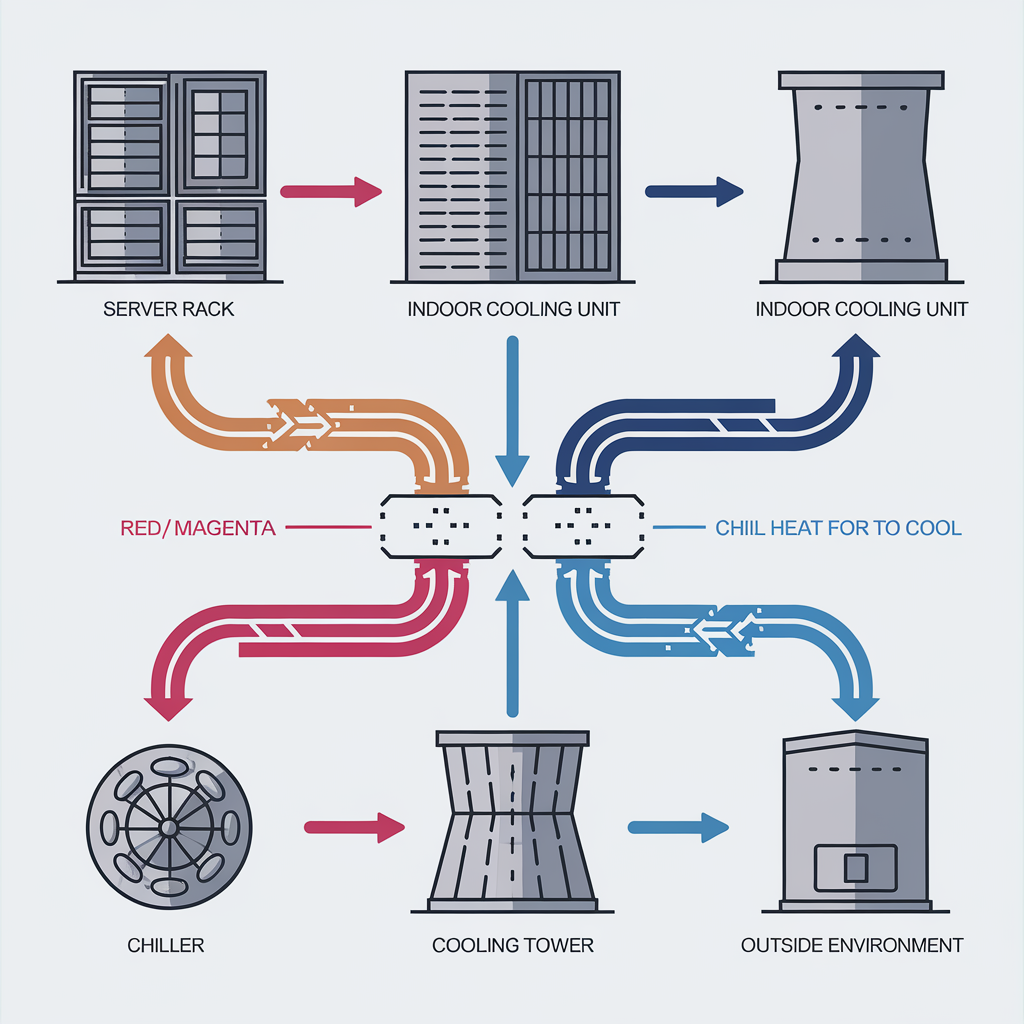
Heat travels through multiple stages to exit the facility.

Inside the Rack: Server Thermal Management

The cooling challenge starts within the server itself. Every processing cycle generates heat. Key components and concepts here include:

  • >_ **Chip TDP:** The thermal design power specifies max heat output (now exceeding 1.5kW for some AI chips).
  • >_ **TIM & Heatsinks:** Materials and structures that draw heat away from the chip surface. Larger chips need larger heatsinks, impacting server size.
  • >_ **Server Fans:** These move air across heatsinks and expel hot air. Their power consumption is significant and scales non-linearly with speed (Fan Law).
Delta T (ΔT): The temperature difference between air entering and exiting the server rack. A higher ΔT indicates efficient heat capture, potentially allowing lower airflow and fan energy.

Hyperscalers often design custom servers to optimize airflow paths and minimize fan energy use, leveraging techniques related to maximizing Delta T.

Simplified diagram showing server components involved in cooling: CPU/GPU chip, TIM layer, Heatsink structure, and Fans. Use labels and subtle glowing effects on heat sources/flow.

Internal components manage heat at the source.

Data Hall Airflow: Controlling the Environment

Once heat leaves the server (as hot air), managing its movement within the data hall is critical to prevent it from mixing with the cold air supply.

Core Techniques:

The "Four Delta Ts": A diagnostic model to break down temperature differences across the data hall airflow path and identify mixing inefficiencies.

Effective airflow management allows datacenters to operate at higher server inlet temperatures (within hardware tolerances, often above 30°C), which enables more efficient facility-level cooling.

Technical diagram showing airflow in a data hall with hot aisle containment. Illustrate cold air supply (blue arrows), servers, hot air exhaust into a contained aisle (red arrows), and return path to cooling units. Use clear labels and contrast.

Containing hot air prevents mixing and saves energy.

Inside the Hall: Cooling Units

These units sit in or near the data hall and are the first point where heat is typically transferred from air to a liquid medium.

Main Types:

An increasingly popular intermediate solution for rising rack density is the **Rear-Door Heat Exchanger (RDHx)**. These are water-filled radiator doors on the back of racks that capture server exhaust heat directly. They reduce the need for room-level cooling and support densities of 30-50kW+ per rack. They often require a **CDU (Coolant Distribution Unit)** to manage water flow and temperature.

RDHx: An in-rack heat exchanger using water to capture server heat directly from exhaust air.
CDU: Manages flow, temperature, and pressure for liquid cooling circuits, often used with RDHx or Direct-to-Chip cooling.
Icons or simple diagrams representing CRAC, CRAH, Fan Wall, and RDHx units. Show air in/out and liquid connections, highlighting how heat is transferred from air to liquid at this stage.

Different units transfer heat from the air in the data hall.

Facility Level: Chillers and the Refrigeration Cycle

Chillers are central to many water-based cooling systems. They use a refrigeration cycle (Evaporation, Compression, Condensation, Expansion) to produce the chilled water needed by CRAHs or CDUs. They are often the most energy-intensive component outside of IT.

Main Types:

COP (Coefficient of Performance): Chiller efficiency metric (Cooling Capacity / Energy Input). Higher is better.
Simplified schematic of a chiller unit showing the four key stages of the refrigeration cycle (Evaporator, Compressor, Condenser, Expansion Valve) using simple icons and arrows. Show water loops connected to the Evaporator and Condenser.

Chillers use refrigeration to cool the facility water.

Outdoor Stage: Cooling Towers & Water Use

Cooling towers are the final heat rejection point for water-cooled chiller systems, transferring heat from the facility water to the outside environment. This stage significantly impacts water consumption.

Types & Water Impact:

WUE (Water Usage Effectiveness): Liters of water used per kWh of IT energy. A critical environmental and operational metric.

Selecting between wet and dry towers, or employing techniques like **Adiabatic Cooling** (misting air before it hits dry coils/chillers), depends heavily on local climate and water availability.

Simplified diagram comparing Wet (Evaporative) and Dry Cooling Towers. Show water spray and visible evaporation for wet, fanned coils and air flow only for dry. Highlight water consumption difference.

Cooling towers are where heat meets the outside world.

Beyond Rejection: The Potential of Heat Reuse

Instead of simply releasing waste heat, some datacenters explore Heat Reuse – capturing the heat from warm facility water and transferring it for beneficial use, such as heating nearby buildings (district heating).

Considerations:

While geographically dependent, Heat Reuse represents a significant step towards more sustainable and integrated datacenter operations.

Conceptual diagram illustrating datacenter heat reuse. Show a datacenter icon connected by pipes to icons representing homes or other buildings receiving heat. Use arrows to show heat flow.

Waste heat can be a valuable resource.

Ready to Navigate the Datacenter Evolution?

The future of computing demands sophisticated infrastructure. Partner with us to explore innovative cooling solutions that meet the challenges of the AI era head-on.

Discover Our Solutions